 Solutions
 Support
 News
News About Us


-
Product Overview
-
Product Details
-
Data Download
-
Related Products
-12P")
ZN63(VS1)-12P
2. Short circuit protection
3. Controlling
4. Used in residential building, non-residential building, energy source industry and infrastructure.
5. According to the type of instantaneous release classified as follows : type B(3-5)ln, type C(5-10)ln, type D(10-20)ln
Conatct Us
Product Details
Selection
| ZN63(VS1) | - | 12 | P | T | 630 | - | 25 | HT | P210 |
| Name | Rated voltage(KV) | Pole type | Operating mechanism | Rated current(A) | Rated short-circuit breaking current(KA) | Installation | Phase spacing | ||
| Indoor vacuum circuit breaker | 12:12KV | P:Solid -sealing type | T:Spring type | 630, 1250,1600, 2000,2500, 3150,4000 | 20,25,31.5,40 | HT: HandcartFT: Fixed type | P150, P210, P275 |
Note:
ZN63(VS1)-12P adopts a double spring integrated mechanism by default. If a single spring modular mechanism is required, a single spring needs to be added to the model backup;
Operating conditions
1. The ambient temperature is not higher than +40°C and not lower than -15°C (storage and transportation at -30°C are allowed); 2. The altitude is not higher than 1000m;
3. Relative temperature: the daily average is not more than 95%, and the monthly average The value is not more than 90%, the daily average value of saturated vapor pressure is not more than 2.2×10-'MPa, and the monthly average value is not more than 1.8×10MPa;
4. The seismic intensity does not exceed 8 degrees;
5. There is no fire, explosion hazard, serious pollution, Places subject to chemical corrosion and severe vibration.
Features
1. The arc extinguishing chamber and operating mechanism of the circuit breaker are arranged in a front-to-back configuration and connected as a whole through a transmission mechanism.
2. The hermetically sealed pole adopts epoxy resin insulation material to seal the vacuum arc extinguishing chamber and the main circuit conductive components as a whole.
3. The vacuum arc extinguishing chamber utilizes a hermetically sealed pole, enhancing the product's ability to withstand environmental pollution.
4. The operating mechanism adopts a spring-stored energy design, providing both electric and manual energy storage functions.
5. It features an advanced and rational buffer device, ensuring no rebound during disconnection and reducing disconnection impact and vibration.
6. It has advantages such as simple assembly, high insulation strength, high reliability, good product consistency, and maintenance- free operation.
7. The mechanical lifespan can reach up to 20,000 operations.
Technical data
Technical datas are shown in Table
| Item | Unit | Value | ||||
| Rated voltage | kV | 12 | ||||
| Rated insulation level | Rated lightning impulse withstand voltage (peak) | 75 | ||||
| 1min power frequency withstand voltage | 42 | |||||
| Rated current | A | 630 1250 |
630, 1250, 1600, 2000, 2500, 3150 |
1250, 1600, 2000, 2500, 3150, 4000 |
||
| Rated short circuit breaking current(KA) | 20 | 25 | 31.5 | 40 | ||
| Rated thermal stable current (effective value) | KA | 20 | 25 | 31.5 | 40 | |
| Rated dynamicstable current (peak value) | 63 | 80 | 100 | |||
| Rated short-circuit making current (peak value) | 50 | 63 | 80 | 100 | ||
| Rated short-circuit breaking current breaking times | Times | 80 | 50 | 30 | ||
| Secondary circuit power frequency withstand current | V | 2000 | ||||
| Rated operating sequence | / | Opening -0.3s - closing and opening - 180s - closing and opening -180s - closing and opening -180s - closing and opening (40kA) |
||||
| Rated thermal stability time | s | 4 | ||||
| Rated single/back to back capacitor bank breaking current | A | 630/400 | 800/400 | |||
| Mechanical life | Times | 20000 | 10000 | |||
The mechanical characteristic parameters are shown in Table 2
| Item | Unit | Value | |
| Contact distance | mm | 11+1 | |
| Contact travel | 3.3±0.6 | ||
| Average closing speed (6mm~contact closed) | m/s | 0.6±0.2 | |
| Average opening speed (contact separation -6mm) | 1.2±0.2 | ||
| Opening time (rated voltage) | m/s | 20~50 | |
| Closing time (rated voltage) | 35~70 | ||
| Contact closing bounce time | m/s | ≤2 | ≤3(40kA) |
| Three phase opening asynchrony | ≤2 | ||
| Allowable cumulative thickness of wear for moving and stationary contacts | mm | 3 | |
| Main electrical circuit resistance | μΩ | ≤50(630A) ≤45(1250A)≤35(1600~2000A) ≤25(2500A and above) | |
| Contact pressure of closing contacts | N | 2000±200(20kA) 3100±200(31.5kA) | 2400±200(25kA) 4500±250(40kA) |
Opening and closing coil parameters are shown in Table 3
| Item | Closing coil | Opening coil | Note |
| Rated operating voltage(V) | AC110/220 DC110/220 | AC110/220 DC110/220 | The opening coilshall not open when it is less than 30% ofthe rated operating voltage |
| Coil power(W) | 245 | 245 | |
| Normal operating voltage range | 85% -110% rated voltage | 65% -120% rated voltage |
Energy storage motor parameters are shown in Table 4
| Model | Rated voltage | Rated input power | Normal operating voltage range | Energy storage time at rated voltage |
| ZYJ55-1 | DC110 | 70 | 85% -110% rated voltage | ≤15 |
| DC220 |
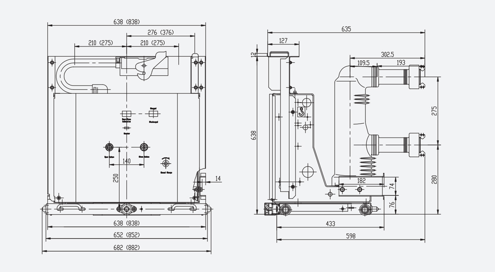
Overall and mounting dimensions(mm)
Handcart type outline size drawing (suitable for 800mm cabinet)
| Rated current (A) | 630 | 1250 | 1600 |
| Rated short-circuit breaking current(KA) | 20,25,31.5 | 25,31.5,40 | 31.5,40 |
| Equipped static contact size (mm) | Φ35 | Φ49 | Φ55 |
Handcart type outline size drawing (applicable to 1000mm cabinet)
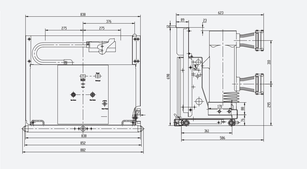
| Rated current (A) | 1600 | 2000 | 2500 | 3150 | 4000 |
| Rated short-circuit breaking current(KA) | 31.5,40 | 31.5,40 | 40 | ||
| Equipped static contact size (mm) | Φ79 | Φ109 | |||
Fixed outline size drawing (for 800mm cabinet)
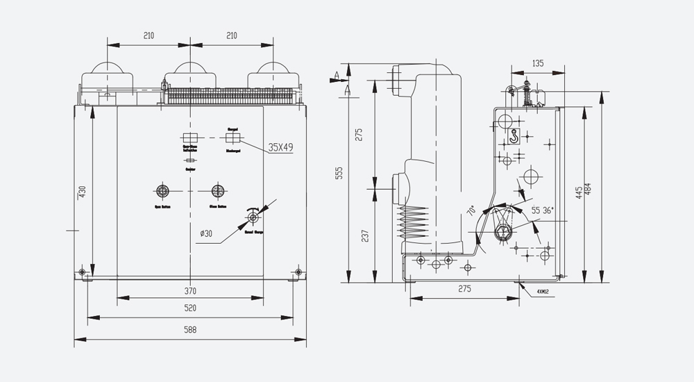
| Rated current (A) | 630 | 1250 | 1600 |
| Rated short-circuit breaking current(KA) |
20, 25, 31.5 | 25, 31.5, 40 | 31.5, 40 |
Fixed outline size drawing (applicable to 1000mm cabinet)
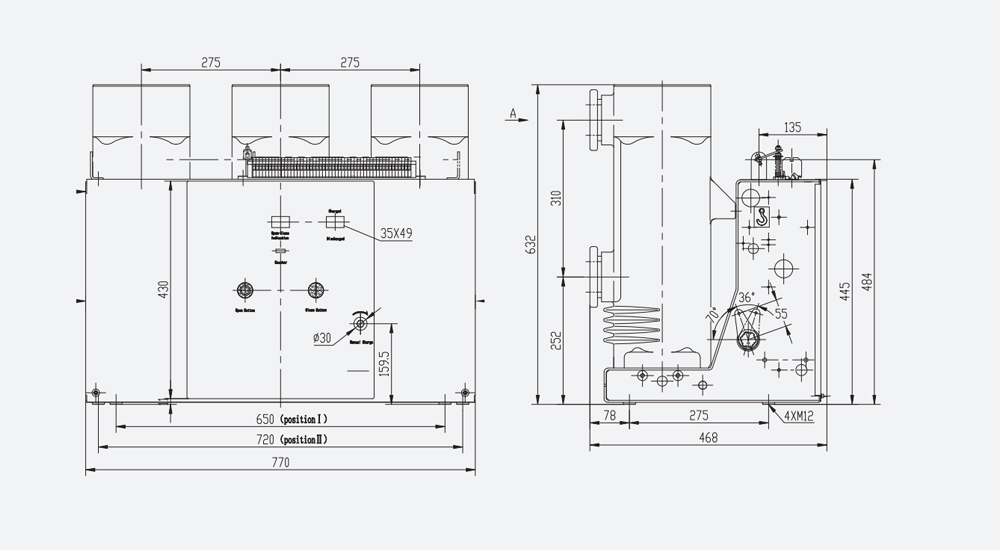
| Rated current (A) | 1600 | 2000 | 2500 | 3150 | 4000 |
| Rated short-circuit breaking current(KA) | 31.5,40 | 31.5,40 | 40 | ||
Data Download
Related Products
-
 ZW20□-12
 -
 FLN36
FLN36 -
 Polymer Insulators...
 -
-24") ZN63(VS1)-24Selection ZN63 - 24 P / T 630 - 25 HT P210 Name - Rated voltage(KV) Pole / Operating mechanism Rated current(A) - Rated short-circuit Installation Main circuit type Indoor vacuum circuit breaker - 24:24KV No mark: Insulating cylinder type P: Solid-sealing type / T:Spring type 630 1250 1600 2000 2500 3150 4000 - 20 25 31.5 40 HT:Handcart type FT:Fixed type P210 P275 Note: Zn63 (S) adopts a double spring integral mechanism by def...
ZN63(VS1)-24Selection ZN63 - 24 P / T 630 - 25 HT P210 Name - Rated voltage(KV) Pole / Operating mechanism Rated current(A) - Rated short-circuit Installation Main circuit type Indoor vacuum circuit breaker - 24:24KV No mark: Insulating cylinder type P: Solid-sealing type / T:Spring type 630 1250 1600 2000 2500 3150 4000 - 20 25 31.5 40 HT:Handcart type FT:Fixed type P210 P275 Note: Zn63 (S) adopts a double spring integral mechanism by def... -
 JDZ8-3,6,10
 -
 ZW32-24


Hot Products - Sitemap - AMP Mobile
3p Ac Mcb, Mccb Microprocessor Based, 250amp Mccb Circuit Breaker, 6a Elcb, Mpcb, 3 Phase Starter,