 Solutions
 Support
 News
News About Us


-
Product Overview
-
Product Details
-
Data Download
-
Related Products
-12")
ZN63M(VCM1)-12
2. Short circuit protection
3. Controlling
4. Used in residential building, non-residential building, energy source industry and infrastructure.
5. According to the type of instantaneous release classified as follows : type B(3-5)ln, type C(5-10)ln, type D(10-20)ln
Conatct Us
Product Details
Selection
| ZN63M | - | 12 | P | M | 630 | - | 25 | HT | P210 |
| Name | Rated voltage(KV) | Pole type | Operating mechanism | Rated current(A) | Rated short-circuit breaking current(KA) | Installation | Phase spacing | ||
| Indoor vacuum circuit breaker | 12:12KV | No mark: Insulating cylinder type P Solid -sealing type | M: Insulating cylinder type permanent magne | 630, 1250,1600, 2000,2500, 3150,4000 | 20,25,31.5,40 | HT: Handcart FT: Fixed type | P150, P210, P275 |
Note:
The phase spacing of ZN63-12□M is usually P210mm, which is not marked on the model
Operating conditions
1. Ambient temperature: upper limit +40°C; lower limit -25°C.
2. Altitude: altitude not higher than 1000m.
3. Relative humidity: daily average value is not more than 95%, monthly average value is not more than 90%; saturated vapor pressure : The daily average value is not greater than 2.2kPa, and the monthly average value is not greater than 1.8kPa.
4. Earthquake intensity: less than 8.
5. The amplitude of electromagnetic interference induced in the secondary system does not exceed 1.6kV. This product complies with relevant national standards and The industry standard requires that it be installed in a place without fire, explosion hazard, corrosive gas and severe vibration.
Features
1. The arc extinguishing chamber and operating mechanism of the circuit breaker are arranged in a front-to-back configuration and connected as a single unit through a transmission mechanism.
2. The operating mechanism employs a permanent magnet mechanism and has functions for electrically closing and opening the circuit as well as manually emergency tripping.
3. The permanent magnet mechanism adopts a dual stable state form, characterized by intelligence, high reliability, long lifespan, and maintenance-free operation.
4. During the operation of the circuit breaker, the energy of the permanent magnet mechanism is transferred to the linkage mechanism,which then transmits it to the moving contact part.
5. The control circuit module exhibits high reliability and can withstand harsh conditions such as lightning strikes and surges during operation.
6. The energy storage module adopts capacitor energy storage, characterized by short energy storage time and long lifespan.
7. The mechanical lifespan is not less than 20,000 cycles.
Technical data
Technical datas are shown in Table 1
| Item | Unit | Value | ||||
| Rated voltage | kV | 12 | ||||
| Rated insulation level | Rated lightning impulse withstand voltage (peak) | 75 | ||||
| 1min power frequency withstand voltage | 42 | |||||
| Rated current | A | 630 | 630, 1250, 1600, | 1250, 1600, 2000, | ||
| 1250 | 2000, 2500, 3150 | 2500, 3150, 4000 | ||||
| Rated short circuit breaking current(KA) | KA | 20 | 25 | 31.5 | 40 | |
| Rated thermal stable current (effective value) | KA | 20 | 25 | 31.5 | 40 | |
| Rated dynamicstable current (peak value) | 50 | 63 | 80 | 100 | ||
| Rated short-circuit making current (peak value) | 50 | 63 | 80 | 100 | ||
| Rated short-circuit breaking current breaking times | Times | 30 | 30 | 30 | ||
| Secondary circuit power frequency withstand current | V | 2000 | ||||
| Rated operating sequence | / | Opening -0.3s - closing and opening - | ||||
| 180s - closing and opening -180s - closing | ||||||
| and opening -180s - closing and opening (40kA) | ||||||
| Rated thermal stability time | s | 4 | ||||
| Rated single/back to back capacitor bank breaking current | A | 630/400 | 800/400 | |||
| Mechanical life | Times | 20000 | 10000 | |||
The mechanical characteristic parameters are shown in Table 2
| Item | Unit | Parameter |
| Contact travel | mm | 11±1(Solid-sealing 9±1) |
| Contact overtravel | mm | 3.0±0.5 |
| Closing speed | m/s | 0.6±0.2 |
| Opening speed | m/s | 1.0±0.2 |
| Contact closing bounce time | ms | ≤2 |
| Three phase closing and opening asynchrony | ms | ≤2 |
| Closing time | ms | 20≤t≤75 |
| Opening time | ms | 13≤t≤65 |
| Permanent magnet drive power supply voltage | V | DC220 |
| Energy storage time | s | <10 |
| Closing control voltage | V | AC/DC 110,AC/DC 220 |
| Opening control voltage | V | AC/DC 110,AC/DC 220 |
| Main circuit resistance | μΩ | ≤45 |
| Phase spacing | mm | 150/210/275(40kA) |
Overall and mounting dimensions(mm)
Handcart type outline size drawing (suitable for 800mm cabinet)
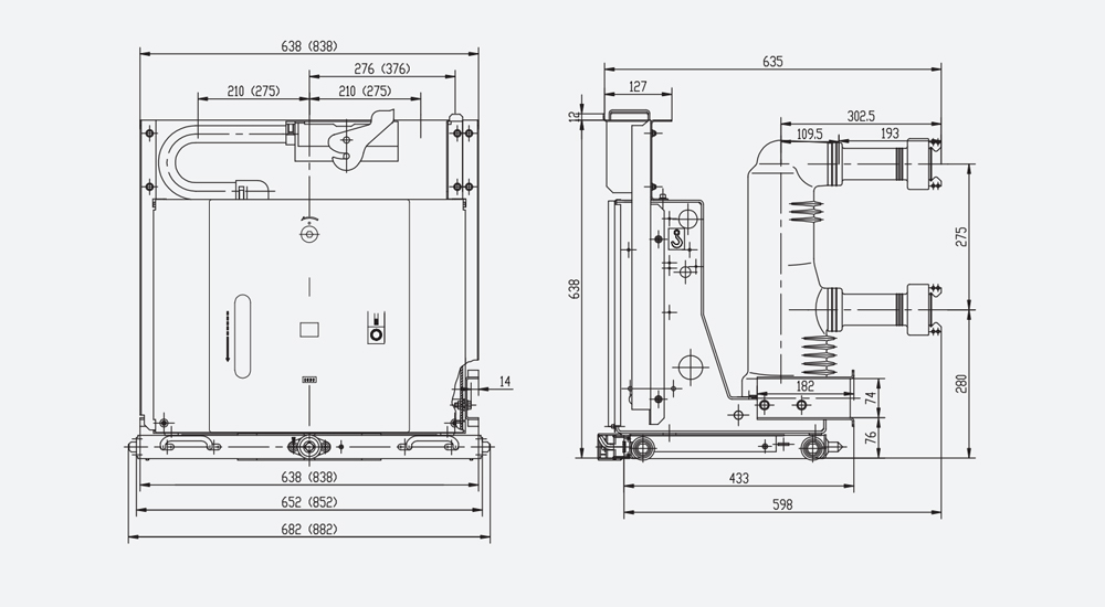
| Rated current (A) | 630 | 1250 | 1600 |
| Rated short-circuit breaking current(KA) | 20,25,31.5 | 25,31.5,40 | 31.5,40 |
| Equipped static contact size (mm) | Φ35 | Φ49 | Φ55 |
Handcart type outline size drawing (applicable to 1000mm cabinet)
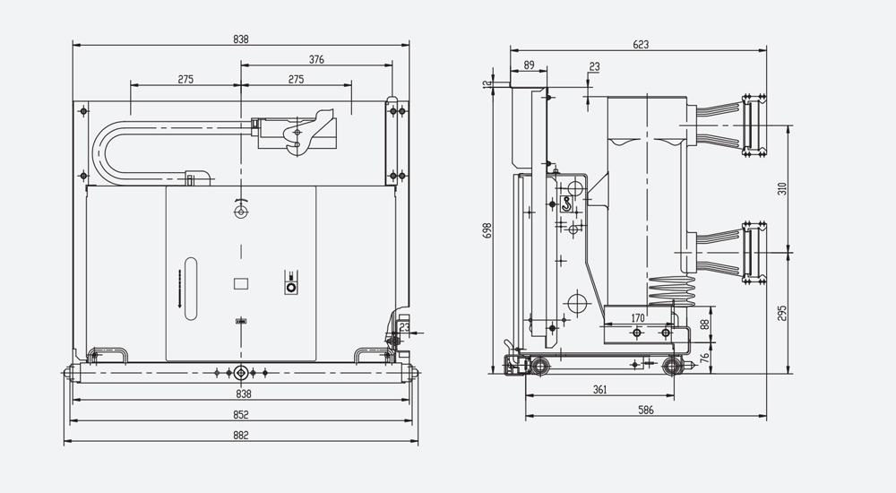
| Rated current (A) | 1600 | 2000 | 2500 | 3150 | 4000 |
| Rated short-circuit breaking current(KA) | 31.5,40 | 31.5,40 | 40 | ||
| Equipped static contact size (mm) | Φ79 | Φ109 | |||
Fixed outline size drawing (for 800mm cabinet)
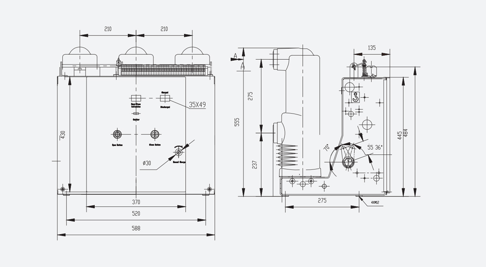
| Rated current (A) | 630 | 1250 | 1600 |
| Rated short-circuit breaking current(KA) | 20, 25, 31.5 | 25, 31.5, 40 | 31.5, 40 |
ZN63(VS1) -12 s fixed outline size drawing (for 1000 mm cabinet)
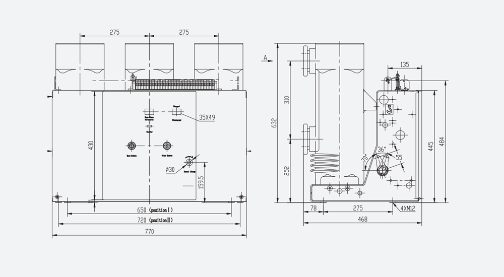
| Rated current (A) | 1600 | 2000 | 2500 | 3150 | 4000 |
| Rated short-circuit breaking current(KA) | 31.5,40 | 31.5,40 | 40 | ||
Data Download
Related Products
-
 XRNT
XRNT -
 GW1
GW1 -
 JN15-24
 -
-3,6,10(Q)") JDZ(J)-3,6,10(Q)
JDZ(J)-3,6,10(Q) -
 JDZ8-3,6,10
 -
 GN19-12 Indoor isolation switchGN19-12 indoor MV isolation switch series MV switch equipment used for rated voltage 10kV, AC 50Hz and below power system, equipped with CS6-1 type manual operating mechanism, open, close the circuit in the case of no load, voltaged. There are derivatives such as anti pollution, high prototype and added charged display device type, etc. Technical data Model Rated voltage(kV) Maximum voltage (kV) Maximum current (A) 4S thermal stability current (kV) Dynamic stability current (kV) GN1...


Hot Products - Sitemap - AMP Mobile
6a Elcb, 250amp Mccb Circuit Breaker, Mccb Microprocessor Based, 3 Phase Starter, 3p Ac Mcb, Mpcb,